Zen and the art of using CAD CAM software. These are the random musings and opinions of someone that has been involved with CAD CAM software since the latter part of the 1980's.
This blog is meant to be light-hearted, informative and balanced.
You have Fusion 360 installed, what's the first thing you should do? Everybody will have their own opinion. One thing you could do first is set your Default Modeling Orientation. When you think of the TOP view of your model, do you normally associate that with the Z axis of your part or the Y axis? The default model orientation in Fusion is set so that Y is the normal direction for the top view. If you work in certain industries or do a lot of manufacturing, you may prefer to have the Z-axis be normal to the top view. Here is our video for our very first Fusion 360 tip.
Special thanks to GrabCAD, where I grabbed the model, and Scott Russell that put it there.
Originally this was going to be a two-part blog, design the knife and then make the knife. However, because of a few issues, specifically, the knife is larger than the travel on our mill, we decided the fixture was a bit more involved. Creating the fixture is now Part 2, and Part 3 will be the actual creation of the knife. For the complete video, click below:
First a big shout out to James on our marketing team, as he has access to a 3D printer, and printed me a sample knife so I could see if I wanted to make changes to the design. After getting the sample, I decided to refine the contour a little, adjust the hole diameter, and space the holes better. Visit James' blog UnprofessionalEngineering the podcast is pretty good, even if he hasn't had me on as a guest yet.
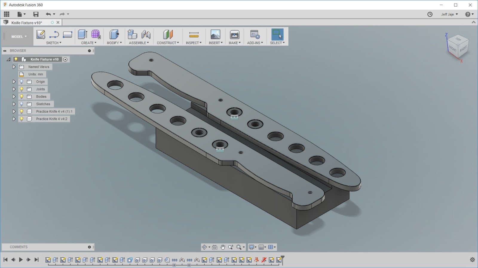
Since the knife is longer than the "X" Travel on our mill, we will have to cut half of it, flip it around, and cut the other half. I'd like to be a little bit more productive in this task, so I designed a fixture to hold two pieces in the mill. First we started with a simple rectangular shape.
Next we create a slot, so the knife will be supported by the raised portions, so the tool has clearance to position the bottom of the tool below the bottom of the knife stock.
From there, we add two bosses, which are the same size and distance as the first two holes in the knife design. This will be used to locate the knife.
Then we create a tapped hole in the center of the bosses, so we can screw the knife stock down.
From there, we drag and drop our part into the fixture drawing, and use an Assembly > Joint command to locate them together.
When complete, and assembled, the fixture, with parts ready to mill, will look like the image below. I'm using an aluminum strap, with the 5/16 bolts, to hold the parts down. I figured this was the best way to reduce vibrations of the relatively thin aluminum bar stock.
In part 3, we will mill the knives, and finish up. I hope you enjoyed this blog, and please leave a comment on anything you'd like to see designed or made.
Many people that practice and study the martial arts, eventually practice with a training knife for instruction relating to bladed weapons. This is especially true if you practice a style that specializes in knife fighting, such as many of the Indonesian and Filipino systems do.
For this blog, we wish to manufacture some of our own training knives, as the class size is growing and we need some more. We already have some sample blades, and some extra material that may work out nicely.
We are not attempting to create the original blade exactly, but rather make a design that is just as functional, but is our own and works within the material we already have on hand.
We have already recorded a video of our design, and you can watch it below:
Original
Below is an image of the original blade, and the material we already had in stock to create a training knife. Thickness is the same, but the stock is not quite as wide, meaning the finger guard will likely end up being a little smaller. In reality, the finger guard is very important to your own safety, but for the training knife, what we have should suffice.
Start Designing
There are many ways of designing this, and this is just one method. Here we started by making a sketch rectangle the size of the blank. We used the Tab key to go from the height to length dimensions. You can also perform arithmetic expressions in the dialog box.
Add Arcs
We then used the 3-pointy Arc command to create an arc shape at the top and bottom of the blade. Since we don't need to follow any kind of print exactly, we are going for an aesthetic shape, that will be safe in use.
Spline the End
Because these will be used in training, we want the end to be blunt and have no sharp corners. In this case, we used the spline command to make a curve that s a rounded end. After making the spline, we forced a tangent constraint. The advantage of using the spline is that we can push and pull it to make the blade longer, and it maintains a smooth shape and the tangency at all times.
Working on the Grip
From there, we work on the grip by filleting the corners on the pommel, and adding two lines and a 3-point arc for the grip.
More fillets and circles
We finish the grip by creating more fillets in all the corners. Then for the holes in the blade, they can be added as a hole after the solid is made, or they can be added as part of the sketch as a circle. In this case, we added some circles to be used as holes in the blade.
Extrude into a solid
Lastly, we will extrude the sketch profile into a solid, making it 6.35mm thick. To further add safety, we can add a chamfer to the top and bottom profile of the blade.
Stay Tuned:
In our next video, we will program and mill the training knife on a CNC milling machine.
We hope you have enjoyed this video and blog, and feel free to ask any questions.
Pretty much immediately after the IMTS show ended in September, the Fusion CAM challenge, part two, was announced. This contest had a significant grand prize, a free pass to Autodesk University.
A 3D model was uploaded in the Autodesk Fusion library, and people had a little over a week to do what they want to actually make the part. They could modify the model, make changes, scale the part, whatever. Users could be as creative as possible. The original part is shown below:
Fusion and Autodesk HSM users are incredibly creative, abd there were a large assortment of parts submitted through the Instagram hashtag #FusionCAMChallenge.
Although the contest has ended, the hashtag still sees some action on Instagram: Follow this link to see some images with the tag.
You can see Curtis Chan's blog post on who won the challenge here: Fusion 360 Blog
Challenges like this really allow others to see the creativity of the manufacturing community, as well as build community.
Autodesk employees get in on the action too. In this case, we decided to mill the shape into a clock. Our mill is the Tormach 440 PCNC. This mill is small enough to fit inside your garage or basement, yet powerful enough to mill metals like steel and titanium. This mill has a travel of approximately 10x6 inches, so we picked up some 1x6 walnut wood to make a clock with a 5.25" diameter. Starting with a 3/8" mill, we rough the back side, including milling a pocket for the clock mechanism.
After roughing the top, we switch to a 1/4" flat mill. This was first used to automatically re-rough some areas that the 3/8" tool was too large to fit into. After that, we use the same tool to profile the shape and finish the horizontal flat faces. This is an important feature. It usually works best to rough with a larger tool, because it is sturdier and you can have higher SFPM removal rates. Then use a smaller tool just for the areas left over. This approach normally allows for shorter overall run times.
After the automatic re-roughing, we used a ball nose to finish the "F" of the clock. Drill a hole for the stem and it's finished. All told, a person with just a little experience with Fusion could program this clock and mill it in a pretty short amount of time. Download Fusion and create your own Fusion CAM Challenge. Below are some images of the clock.
Is it possible to make soft jaws from plastic materials like Delrin? How much will they deform when tightening a vise? Will they work well enough on parts where you are taking light cuts?
While looking for small blocks of material that can be used for milling some sample pieces, we found some Delrin which was the correct height and thickness. They only needed to be cut to length, and have the counter bore holes added. We did this easily in Fusion 360 and performed the milling on the Tormach 440. We'll continue this discussion later, once we have a chance to test them on a real part. Until then, here's a little video of the machine in action. Follow the progress on Instagram. Autodesk.mfg account or my personal account.
Today's post is going to be a really short one. We are at the IMTS show in Chicago this week. You can find us at the Autodesk booth E-3222. One goal is to be able to do some follow up posts after the show, what's new, what was drawing excitement, etc. But until then, my good friend Lars from www.cadcamstuff.com used a day walking the show to put together a video for everyone.
Guess what? We have a small CNC mill here at the Zen Labs. It's a Tormach 440. Capable of milling hard materials like steel. I made a very rough video showing the mill, and doing a simple engraving. We will have more detailed updates in the future, but I was excited that everything was working, and wanted to get a quick video up. See the video here:
What should we mill? Post your ideas in the comments.